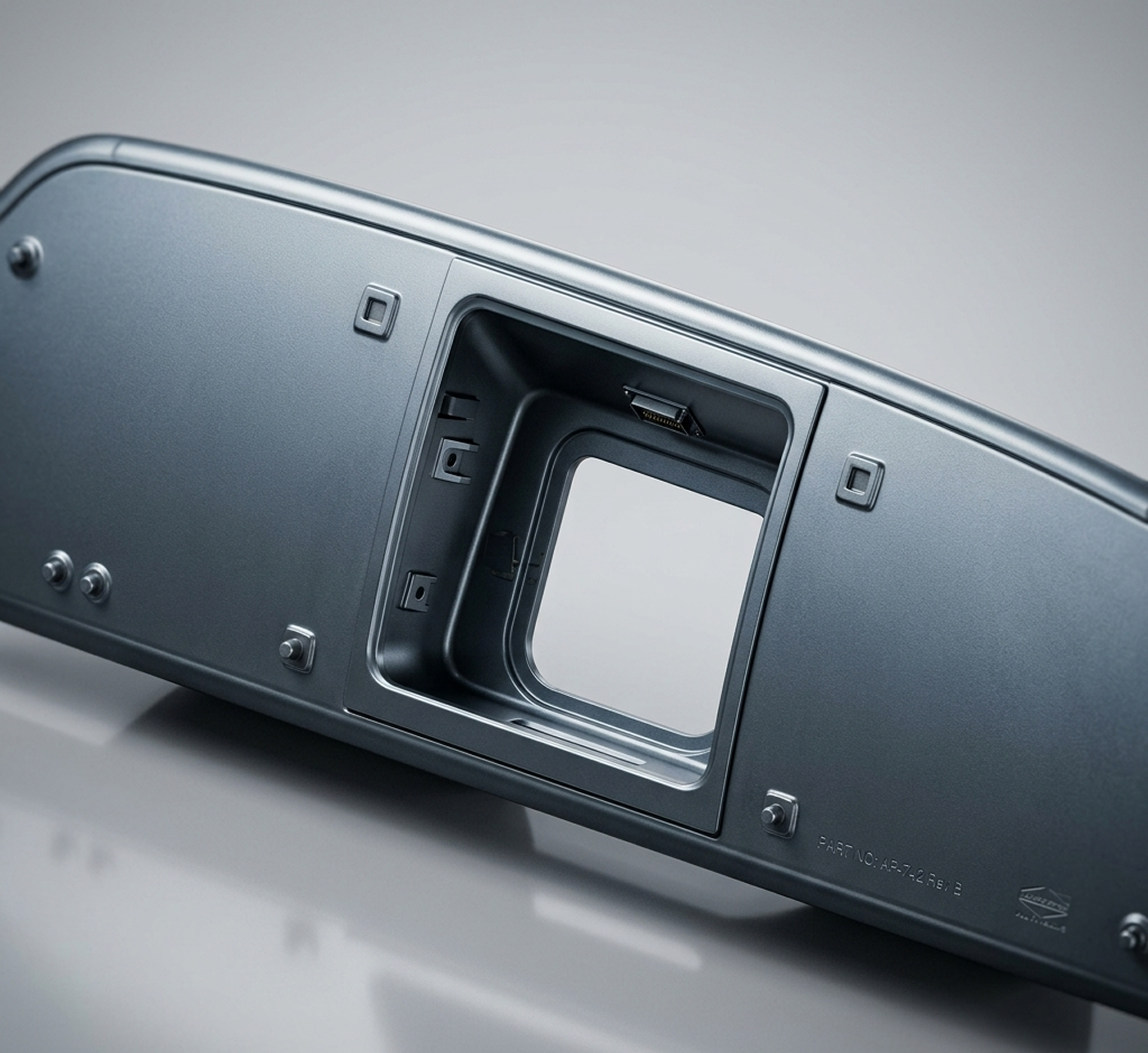
Automotive Glass
When loading and unloading items into the bed of a pick-up truck it is typical for the rear glass to get damaged. So, an aftermarket automotive glass manufacturer took notice and wanted to develop and mass-produce an after-market product. To achieve their goal, the OEM automotive glass had to be reverse-engineered. Applications 3D was contacted to assist them with this task for the Toyota Tacoma.
Automotive Glass Reverse Engineering Process
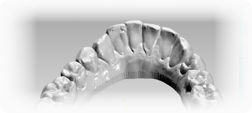
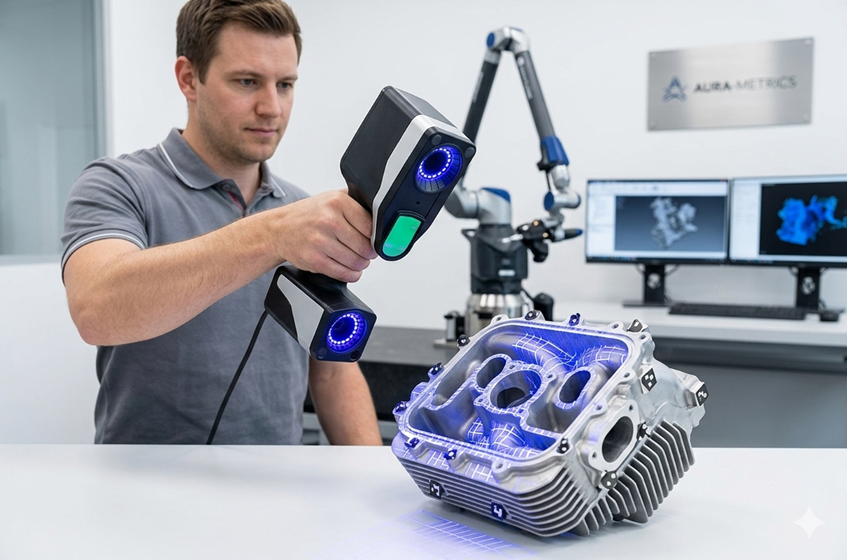
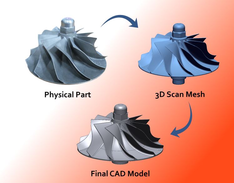
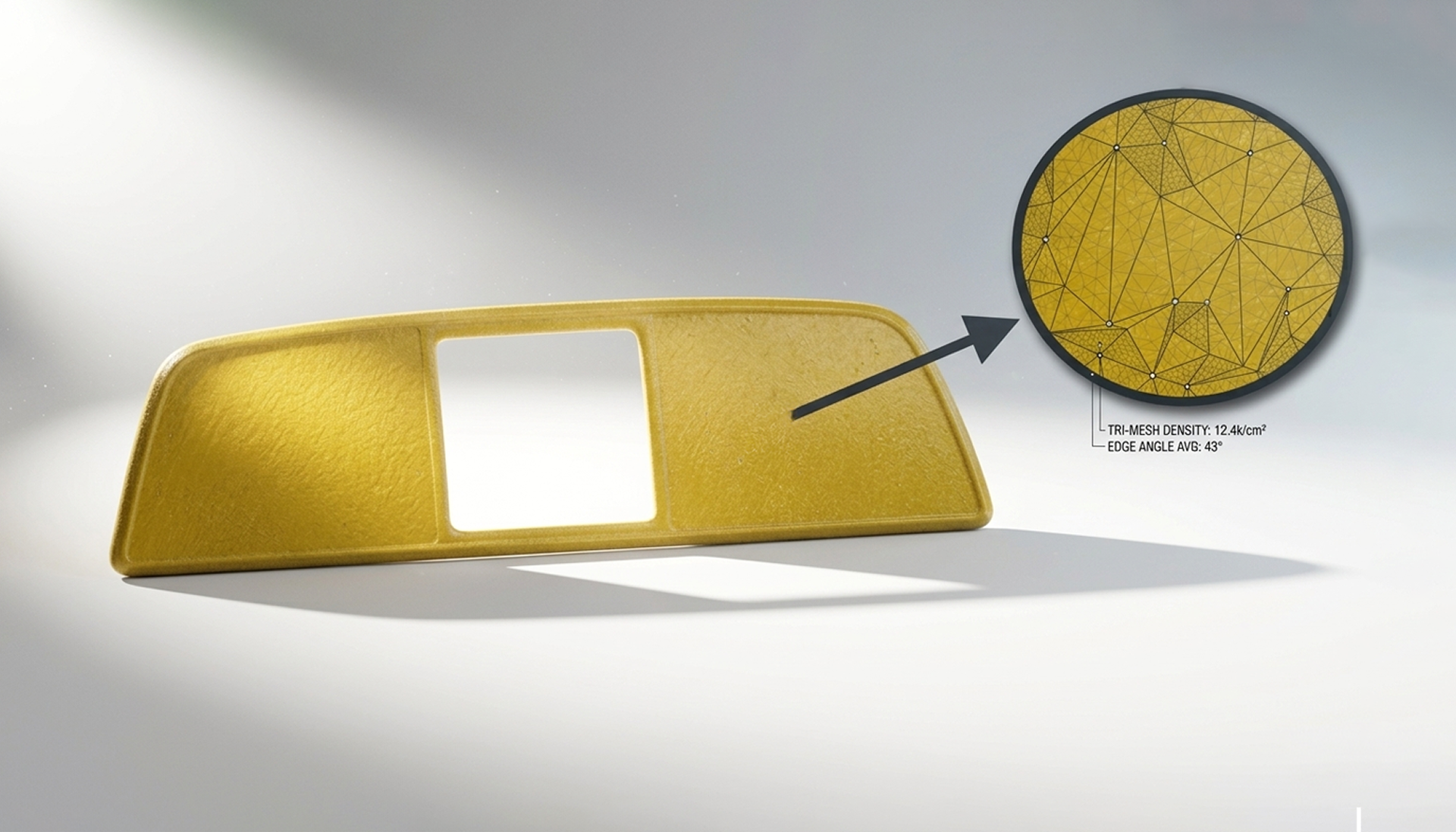
The initial step in the reverse engineering process is to 3D scan the OEM piece. Since high-accuracy scan data is required, this was accomplished by utilizing the Comet White Light Scanner. This scanner, however, will not recognize the glass due to it being transparent. So, to achieve the highest data quality, a chalk-like spray is used across the entire piece. This ensures that the glass gets scanned as well and also improves the data quality. Additionally, the part does not get damaged by the spray and it is easily removed. The 3D scan data is a collection of millions of points all over the surface of the part. Further, each of these points is a vertice for a triangle and has its individual x,y & z coordinates. When combined together, it is commonly called a point cloud. Finally, the millions of triangles are processed together into a single triangular mesh skin and exported as a STL model. Also, this scan data is thoroughly inspected to ensure all the data required for reverse engineering has been acquired.
Modeling the OEM Part
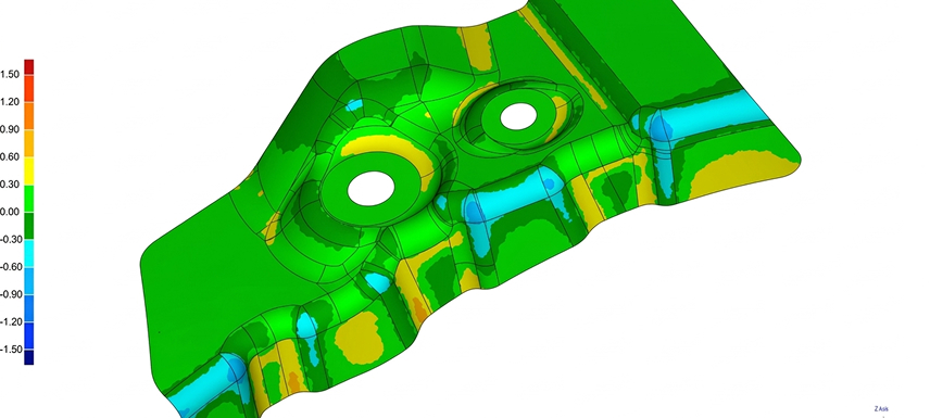
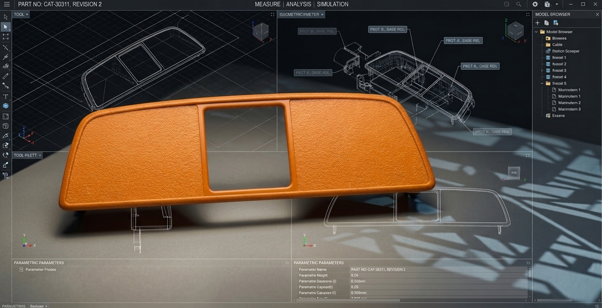
With the scan data acquired, automotive glass reverse engineering can begin. The scan data will be utilized to create a CAD model. Since the scan data needed to be utilized, this CAD model was created using specialized Reverse Engineering software, which can handle high-resolution, large-sized point clouds or STL models. Additionally, each surface was created using feature-based modeling, blended, edited, and stitched together to make a solid model. Lastly, the finished model is tested for accuracy and looks. Firstly, a color map is utilized to relate the surface of the CAD to the scan data. Furthermore, this ensures that the CAD model is highly accurate to that of the OEM part scan. Finally, utilizing zebra stripes to ensure that the part has full G2 curvature continuity for Class A looks. Additionally, a challenge within the project was the fact that the OEM part had a sliding window. Surely, the slot for the sliding window had to be highly accurate. This is so that it operates smoothly and can also create a seal with the rest of the glass. Nevertheless, this challenge was overcome and a high-quality product was produced.
Request A Quote
Please fill out the form below, and we will get back to you within the hour.

Phone
(248)853-7700
Innovation Brought to Life
Past Projects
Our past projects highlight real examples of how our 3D scanning, inspection, reverse engineering, and CAD design services solve complex manufacturing challenges. These case-driven results demonstrate our expertise across automotive, aerospace, medical, and tooling industries.